Wednesday, November 24, 2010

Windshield wipers

So in my car I've had an issue with my windshield wipers since the beginning.  The park function didn't work, I would turn off the switch and they would stay exactly in that spot, quite annoying.  So I figured I would take the motor out and see what I could do to fix it.

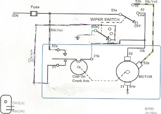
After reading through Speedy Jim's wiring on windshield wipers, I realized I've got a motor from a bug with steering column mounted switch like this:

It was the green wire that gave it away.  But my car is a '68 with dash mounted switch like this:


So after figuring out the differences in the wiring, in theory it should be fairly simple to make the motor with the green wire hookup the same as the motor without.  A few mods would be necessary to make them behave the same, they are like this:


As you can see I had to cut the ground wire from pin 31 on the cam.  I also had to cut the green wire on 31b to 53e.  Then to make the hookups, I routed pin 31 on the cam to the park side of the switch, on my switch it is pin 31b.  pin 31b on the cam the is hooked up to pin 53 on the motor.  The last thing is 53e on the switch will need to be grounded.

So here is a before and after picture:

This is how it came out of the car.  
Wiring is as follows, left to right:
Green, Black/yellow, Black, ground, black/grey


This is after the mod is done.  As you can see it is only a little bit different.
Wiring as follows, left to right:
Green jumped, black/yellow, black with green jumper, ground removed; changed to brown, black/grey


I tested the motor without a switch last night and it works as planned, so tonight I hope to get the switch hooked up for the final test.

Saturday, November 20, 2010

VR sensor mount

So I've had a mount that I made for the VR sensor for the Megajolt system for a while now.  The other day I decided it wasn't nice enough, so I spent some time cleaning it up with the die grinder, hand files, a little bit of glazing putty and sand paper.  After a few nights of work and waiting for the putty to dry, I put a first coat of paint on it.


I think it looks pretty good, especially since it's just some old angle iron welded up.

Also, just though I'd show what my trigger wheel mount looks like.


I started by using my old degree pully (kinda beat up, I know), I took a piece of aluminum bad and using the lathe spun it down to make three stand offs that you can see in the pics above.  The part touching the pulley is about 1/4 inch bigger than the smaller part.  That gives the trigger wheel something to sit on.  The smaller portion is perfectly fit (well as perfect as I can do free hand) inside the wheel circumference, this allows the trigger wheel to spin freely to align with however I choose.  Then the hex key bolts and washers tighten up and hold everything in place.

It seems to work well so far.

Gotta love the lathe

So I was trying to decide how I wanted to hook my balance tube and my MJLJ together.  So I decided to make an adapter/reservoir out of some aluminum tube I've got.

I've used the tube for other things too, like fuel pump block off, distributor block off/case vent.

So here is a pic of it

The only crappy part about this sexy piece is, you'll never see it unless the engine is out of the car, or you look at pics ;)

Oh well, it's still nice, and functional, so I'm happy.

Sunday, November 14, 2010

Some engine pics

Just thought I'd share some pics of the engine so far. 


Saturday, November 13, 2010

New power supply and bluetooth added

Well while I wait for my new FTDI breakout board I thought I'd redo my power supply.  So I've gotten rid of the linear 7805 regulator and switched to a MC34063l dc-dc converter.

You can see on the bottom of the pic is the new power supply, much nicer looking, and more efficient.  Plus, the new protoboard fits in the exact same mounting holes as the old one (complete fluke) 

Here is a closer look with it powered up.

Also new in the work is the bluetooth, currently it doesn't do anything, but I'm hoping that once I get the ability to program the board back I will use it to pass info back and forth about sensors, outputs and the like.

Tuesday, November 09, 2010

Just a note

I have been working on this project for the last 9 months or so, but I've just begun documenting it, so I will try to get as much info as possible, if you want to see something in particular or whatever, just ask.

Arduino broken

Well the other day I was programming away on the Arduino, finally got the GPS to work with the LCD as I had been hoping for, and a slight mishap ripped the USB connector right off of the Arduino board.

So, I'm now waiting for a replacement FTDI breakout board to arrive so I can once again upload my sketches to the board.

Oh well, on the plus side, some connectors I ordered from Digikey arrived today.

Wednesday, November 03, 2010

LCD

So for display purposes I have one main LCD in the car 
It is a Matrix Orbital screen that can connect via serial or I2C.  I have chosen I2C.  I2C allows many devices to be hooked up to the same two pins using addresses, similar to how USB works.

As stated above, this will be my main screen for now.  It will show engine information, date/time, speed from GPS unit (which can be seen in the lower left of the picture), iPod song information and whatever else I find necessary.

I also am going to have a small OLED screen from seeedstudio.  It will be placed in the engine compartment and show vital engine stats, such as timing and engine load.  This will be helpful to make sure that what the computer thinks for timing is the same as what it actually is.  Also it will just look cool.

It also speaks via I2C, so no additional pins are required on the mega, just another address.

For my Matrix Orbital, I have a library I found somewhere online and modified for my own use.

LCDI2C library download

Megajolt

As stated before I am using a Megajolt as an ignition controller.  "The Megajolt Lite Jr. (MJLJ) is a fully programmable, stand-alone ignition controller designed to control a Ford EDIS 4, 6 or 8 crank-fired ignition module. The result is a precision, digitally controlled distributor-less ignition system."


I am using this with the Ford EDIS 4, as the VW is a 4 cylinder engine.
My plan is to wire the MJLJ to the Arduino using the built on serial ports.
Since I'm using an Seeeduino mega, I've got 4 serial ports available to use.  The mega will read the serial stream of the MJLJ and display RPM, timing, engine load, and possibly more on the LCD screens I have hooked up.


I will post code to do this when it's ready, in the mean time, sit tight.
This is a MAX233 chip, it converts +/- 12 volt serial to 0/5 volt ttl voltages, this allows the MJLJ to talk to the mega without modification.  I used the 233 instead of a 232 because I'm lazy, and didn't want to bother with charge pump caps, they're built in.

This is the MJLJ, you can kind of see in the top left corner a black plug thing, it is a headphone jack that I've wired into the serial cable, it will normally be hooked up to the mega's serial port via the 233 chip, but, I have made a cable that plugs into it that will disconnect the mega, and re-rotue the serial data to my computer.  By doing that I can reprogram the MJLJ without having to fumble around disconnecting wires.  I will try and get a better picture to show what I've done.


Relay board for Arduino

So in order to make the Arduino* control things in the car, such as lights, I need to use relays.  So I've made a board that hooks up to 32 of the mega's pins and will give a ground connection for the relays.

As you can see, the wires are all soldered to the relay board, and on the other side is a 32 pin male header plug that fits directly into the mega's female headers.  This allows me to disconnect if I ever need to do work with ease.
The row of screw terminals is where the relays connect.  The relay harnesses all connect to each other, and will be mounted somewhere under the hood, and the ground wires will be routed to this board.

The schematic for this is as follows

The protection diode I used is a 1N4007, the transistor is a 2N3904, and the input resistor value is 2.2K Ohm


*actually I'm using the Seeeduino Mega from seeedstudio

Tuesday, November 02, 2010

Arduino interface for my car, Lydia

I've been asked to document the things I have been working on for my car.

I'll start with my ideas, and from there go into more detail in other posts.

The car is a 1968 VW Beetle, I rebuilt the engine, converted to a computerized ignition, and am putting an Arduino into the car to link everything together.

Some of the features I plan on adding are:
-RFID
-Push button start
-Communication with electronic ignition (Megajolt)
-LCD screen
-iPod connectivity
-GPS connectivity
-Temperatur sensors
-Light sensors
-Touch sensors

Engine rebuild

So like I stated I've been working on the engine since Feb 2010.  I know it's a little late to start documentation, but it's better late than never.

So as she lies now, I've rebuilt the engine, using mostly new parts.  The plan was to reuse as much as possible, and the more I learned the less I wanted to reuse.

I've also added disk brakes on all 4 corners, used dropped spindles up front, as well an adjustable beam.  So the drive train is mostly new.

The most recent news on my engine is I had to replace my flywheel, it was old and reused, and it tore up my main seal, causing a major oil leak.  So I replaced the entire clutch and pressure plate while I was at it.
The other thing I'm waiting on is a new alternator, mine is an old 55 amp one, I'm hoping to get a nice new 90 amp version.

As far as that goes, I'll have to wait and see.  I will post more when I know more.