Friday, April 29, 2011

Air Suspension

So I decided to put in an air suspension, it gives nice soft ride while allowing me to achieve the ride height I'm after and also able to take speed bumps. So it's win-win

Compressor

Air bag mount


Front air shocks


Working on the pan


Just some pictures of the pan.  These are from take down and test fitting.  I still have more to cut away and reweld, but it's progress.

Cleaning undercoat

Rust in Napoleon Hat

Framehead bottom removed

Framhead cleanup

New bottom plate test fit

New nap hat ends


Monday, January 17, 2011

Car is apart

Well I have the body off of the car, now it's time to fix all the problems and put it back together.

So I have cut out the floors and have found a lot of rust in the heater channels (to be expected, it's a VW after all) and some in other places.

Hopefully before to long I have it all fixed.

Here are some pics

Where the body mounts to the pan


Passenger side heater channel

Behind the battery tray, passenger side.

Behind the batter tray, drivers side

Passenger side heater channel

Again

Drivers side heater channel

Body mount again

Passenger side again, it's worse than the drivers


Well I'm going to source new parts and get to it, I'll post more when I have more.

Friday, January 07, 2011

Car is coming apart

Well the other day I began the wiring in the car.  What I found in the floors is worse than I remembered.  So I'm going to take the car apart and do a full pan up resto.  It's time to do what I've wanted from the beginning.

So here is the interior mostly stripped, getting ready for body removal.

Saturday, December 11, 2010

New speedo

Well today my speedo arrived.  It is an Autometer NV series 5" speedo.  Here is an idea of what it will look like once mounted


As you can see the dash isn't done.  I also have a matching tach, and will be getting a fuel gauge, and voltmeter too.

Wednesday, December 01, 2010

Arduino fixed

So I finally got my FTDI breakout board I ordered from Sparkfun.  So I hooked it up right away and it works again, finally.

Here is a pic of it

I hooked the Gnd, TX, RX, and DTR pins up.  I didn't hook up VCC, because I only need the FTDI board powered when I want to upload, plus then I can use the USB power to disconnect anything else that is on the same serial port automatically.

So pinout is like this:

FTDI  -  Arduino
Gnd    -  Gnd
TX      -  RX
RX      -  TX
DTR    -  DTR

I also had to remove the solder joint beside the FTDI chip to disable the 3.3 volt, and then I soldered I wire from VCCIO to VCC, which converted everything to 5 volts.

The DTR line is used for the auto reset feature, if you don't care about that, then don't hook it up.  Myself, I want everything to be as automatic as possible.  Once everything is installed into the car I won't have easy access.

Wednesday, November 24, 2010

Windshield wipers

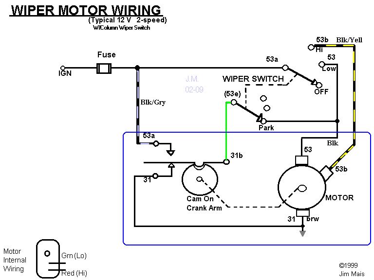
So in my car I've had an issue with my windshield wipers since the beginning.  The park function didn't work, I would turn off the switch and they would stay exactly in that spot, quite annoying.  So I figured I would take the motor out and see what I could do to fix it.

After reading through Speedy Jim's wiring on windshield wipers, I realized I've got a motor from a bug with steering column mounted switch like this:

It was the green wire that gave it away.  But my car is a '68 with dash mounted switch like this:


So after figuring out the differences in the wiring, in theory it should be fairly simple to make the motor with the green wire hookup the same as the motor without.  A few mods would be necessary to make them behave the same, they are like this:


As you can see I had to cut the ground wire from pin 31 on the cam.  I also had to cut the green wire on 31b to 53e.  Then to make the hookups, I routed pin 31 on the cam to the park side of the switch, on my switch it is pin 31b.  pin 31b on the cam the is hooked up to pin 53 on the motor.  The last thing is 53e on the switch will need to be grounded.

So here is a before and after picture:

This is how it came out of the car.  
Wiring is as follows, left to right:
Green, Black/yellow, Black, ground, black/grey


This is after the mod is done.  As you can see it is only a little bit different.
Wiring as follows, left to right:
Green jumped, black/yellow, black with green jumper, ground removed; changed to brown, black/grey


I tested the motor without a switch last night and it works as planned, so tonight I hope to get the switch hooked up for the final test.